Paper Inventions 2nd Edition Sample Lesson
Make a Robot Pressure Sensor with Pencil!
Adapted from the book Paper Inventions 2nd Edition by Kathy Ceceri

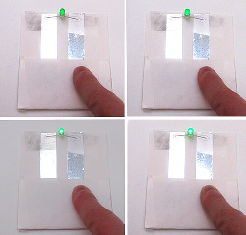

A Pencil Pressure Sensor makes the LED light dim or bright, depending on how hard you press on it!
Scientists have tried pencil to make low-cost pressure sensors to let tell robots know how hard they are pressing on an object. Pencil “lead” contains bits of graphite, which is conductive, held together by clay. Pressing on the pencil scribblings squeezes the pieces of graphite together, improving the electrical connection.
The photo on the left shows the graphite pressure sensor used in laboratory tests. The sensor was attached to the gripper of a Baxter robot (photo on the right taken on a visit to the robotics lab at RPI in 2014).


Supplies
template copied onto an index card or printed on cardstock
3-volt disk battery
2 LEDs (red or yellow preferred)
pencil with soft lead (No. 2, HB, or softer)
conductive tape
clear tape
Instructions

Pressure Sensor template — Draw a copy or click the image for a printable version.
Note: Dotted lines = fold. Solid lines = cut.
Before you start: Test your LED light and battery by insert the battery between the metal wires (called leads) or using a battery tester circuit card. (See Paper Inventions 2nd Edition for how to make one!) If the LED doesn’t light up, reverse the battery.
The positive side of the LED (the longer wire or the side marked with a plus (+) sign) must connect to the positive side of the battery. The negative (-) side of the LED connects to the negative side of the battery. Make sure each side of the LED is lined up with the matching side of the circuit.
Fold the bottom edge of the card up along the dashed line. (See template.) Unfold and flatten.
Cut the bottom flap in half along the solid line.
At the number 3 on the template, stick two strips of conductive tape to make an upside-down “L”. The pieces must connect, so overlap them. This is the negative side of the circuit.
Next, attach the battery. Make a sticky-side-out loop of conductive tape and put it on the negative side of the circuit where shown. Press the battery down on top of the loop, positive (+) side up.
Start the positive side of the circuit by putting a strip of conductive tape on top of the battery and going across the card as shown. Cover the battery with clear tape to secure it to the card.
Leave a gap as shown on the template, and add the rest of the positive side of the circuit.
Time to add the LEDs. Make sure they match the positive and negative sides of the circuit. (There are hidden positive and negative symbols on the robot to remind you. Can you see them?) Attach the LEDs to the circuit by sandwiching them in with another piece of conductive tape. If needed, carefully bend the leads out to the sides.
Finally, take the pencil and color in the area on the bottom flap. Four layers of pencil usually works. Start by scribbling back and forth at an angle, as shown. Then go in the opposite direction, still at an angle. Next, scribble side to side. Finally, try to fill in any spaces left by going top to bottom.
Before you go on, test the pressure sensor by folding up that side of the flap and pushing down hard. Do the LEDs light up? If they do, try using different amounts of pressure to make the LED brighter or dimmer. If they don’t, check out the troubleshooting tips below.
When everything works, use clear tape to close up the battery side of the flap, so it can’t fall out.
Troubleshooting Tips
If your LEDs don’t light up at all, check that:
All conductive material makes a good connection.
The polarity of the LED matches the battery.
The positive and negative sides of your circuit are not touching, which can make it short circuit.
The colored-in pencil "drawbridge" is nice and dark, with long strokes from top to bottom.
The penciled area touches both sides of the gap in the circuit when you fold it up.
To find a break in the circuit, take an extra piece of conductive tape (with the backing paper still on) and touch the ends to the parts you think are not connected. If it makes the LEDs light up, patch the break with another layer of conductive tape.
Want More of Kathy’s Projects?
Check out my other books
Look for more free activities you can do at home on my projects page
Ask about my workshops